Cracking
Cracking Moment
The programme calculates the total axial force and moment from the loads in the analysis case definition. It uses the axial force and the angle of the applied moment to define the cracking moment analysis task. The programme then searches for a strain plane that gives the cracking strain as shown below.
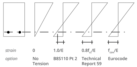
Integrating the stresses from this strain plane over the section will give an axial force equal to the applied force, and a moment which is parallel to the applied moment. The value of this moment is the cracking moment. Short-term material properties are always used for the cracking moment calculation.
Crack-width
Crack width formulae to BS8110 and BS5400 are based on a weighted interpolation between two effects. Close to a bar, crack width is a function of the bar cover, . Between bars, it is a function of the depth of tension zone, .
BS8110 and Hong Kong Code of Practice
Crack widths can be calculated to BS8110 using any of the three available tension stiffening options.
After calculating the cracking moment, AdSec will search for a strain plane which gives forces and moments within tolerance of the applied forces and moments. The resulting strain distribution is used to calculate the crack width.
The maximum crack width output is related to the given resultant moment orientation. This is particularly important for circular sections, as the maximum strain may not occur between two bars.
This would give a lower crack width value than may occur in reality.
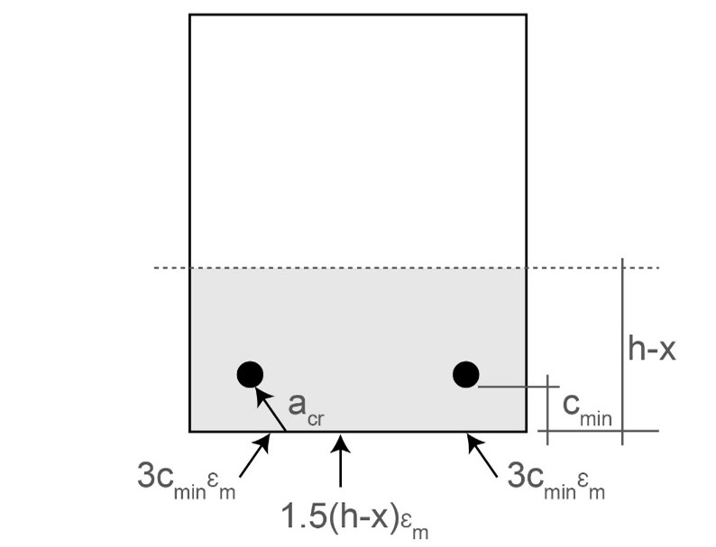
The sides of the section are divided into small segments and the crack width calculated for each segment. The crack width formula
is given in BS8110, section 3.8, equation 12.
Crack width calculations involve a large amount of engineering interpretation for faceted sections, sections with voids, sections with re-entrant corners, and multi-zone sections. Depending on the situation, a different definition of cover is required. The programme stores the minimum cover to each bar and uses this in the calculation of crack width. This means that the cover used in the calculation may not relate to the side being checked (it will always give a conservative result). The reason for this approach is that curved sections are analysed as a multifaceted polygon, and there may be no bars present parallel to a small facet. This is because the number of facets may be greater than the number of bars.
The crack width calculation is done on a zone by zone basis using the zonal strain plane (resulting strain plane + component strain plane + concrete only component strain plane). This component strain plane applied to the whole section is used to calculate neutral axis depth and section height (x and h) relative to the whole section -- using all the section coordinates.
The crack width includes the term . If is smaller than the crack width is increased.
For each division on the concrete outline the closest bar is found (minimum ). For a re-entrant corner, and a bar which is on the outside of the section with ref to the side being checked a warning flag is generated, A conservative crack width can still be calculated using the minimum cover to the bar.
If the cover is greater than half the depth of the tension zone, the crack width in both codes in invalid.
The term for concrete only cracking should be used instead. This is . This is included in AdSec.
These are warning in the crack width calculation. They do not necessarily mean that the answer is wrong. But do mean that the graphical results should be checked for engineering interpretation
-
< controlling bar diameter -- crack width not valid
-
Controlling bar is remote from crack location
-
Controlling bar and crack are located on either side of re-entrant corner
-
Cover to controlling bar measured to different side from crack location
BS5400, Hong Kong Structures Design Manual and IRS Bridge Code
The BS8110 specification above is valid for BS5400 plus some additional points.
The BS5400 includes a fudge for effective tension stiffening. So for crack widths to be correct using the BS5400 formula, SLS analysis must use no tension stiffening in calculation of the strains around the section.
This fudge requires calculation of the level of tension steel. This is re-calculated on a component by component basis using a similar method to BS8110-2 tension stiffening. The tension steel is identified as the steel which is in the tension zone when the zonal strain plane is extended across the whole section (the zonal strain plane is the resulting strain plane + zonal locked in plane + zonal concrete only plane). From the steel bars identified, the centroid of steel force is calculated using the actual stress in the bars ignoring prestress and ignoring any bars in compression.
Once the level of centroid of tension steel is found, the width term needs to be calculated. This includes interrogation of all the section coordinates (as for x and h). If more than 2 sides cross the level of centroid of tension steel, the width is taken as the distance between the two extreme dimensions. This needs to be checked for sections with large voids, or channels with thin legs, as the term is used to make an approximation for the force in the tension zone and assess the area of tension steel versus the area of tension concrete. It may be appropriate to substitute a smaller value of .
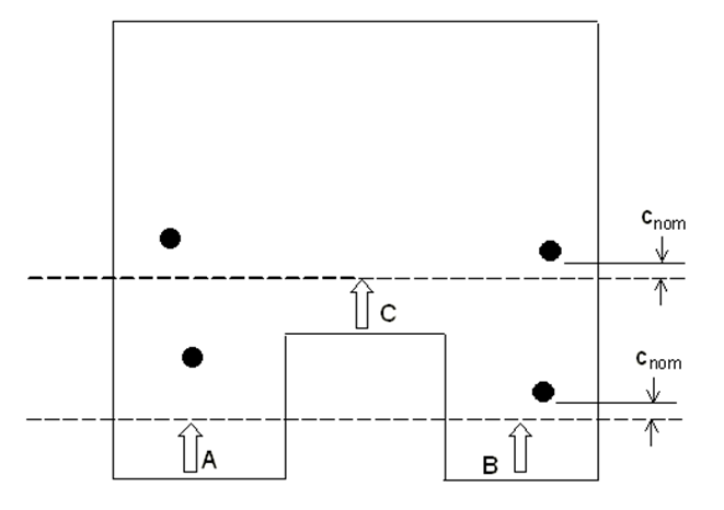
BS5400 includes a notional surface a distance from the bars. AdSec will look at all bars to define this surface excluding any with negative cover. This should be reviewed, particular for sections with sharp acute angles and re-entrant corners. In the example below the adjustment to sides A and side C may not be the adjustment that would be chosen by engineering judgement. In this situation, the cracking parameters output for the relevant sides can be extracted from the output, and the results recalculated, substituting the corrected values.
The crack width equations in BS5400-4, which are offered by AdSec, are either equation 24
where the strain is given by equation 25
or the alternative equation 26