2. Simple beam
Model a beam in GSA
This tutorial will show you how to model a beam in GSA and by the end of this tutorial you should be able to:
- Setup a new model with the new model wizard.
- Create a 1D member, add restraints, section properties and loads to it.
- Analyse and view results.
Create a new model
-
Open GSA and select Setup new model
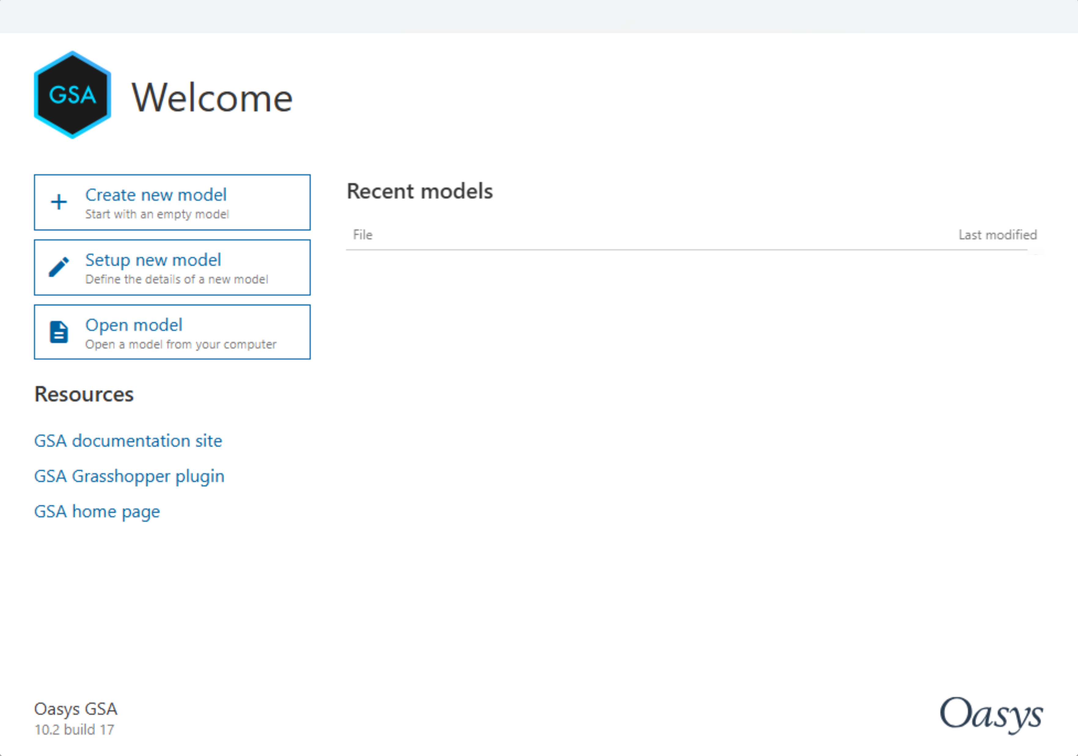
-
This takes you to the New Model Wizard, where you can enter the name of your project or click Next.
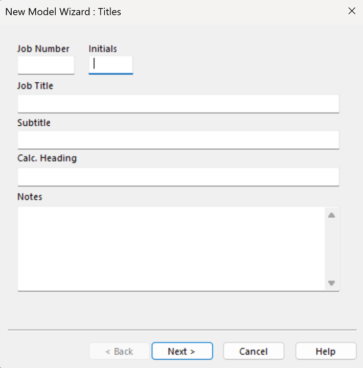
-
Click on Units and choose your preferred units or just leave it and click Next.
-
This takes you to the New Model Wizard: Properties where preferred design codes and appropriate material properties can be defined. For the purpose of this tutorial, we will select Steel code BS EN 1993-1-1:2005 (GB) and Concrete code BS EN 1992-2:2005 (GB). Select Steel grade as S275 and Concrete grade as C40/50.
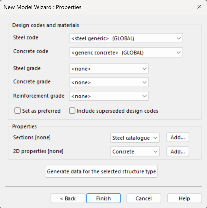
-
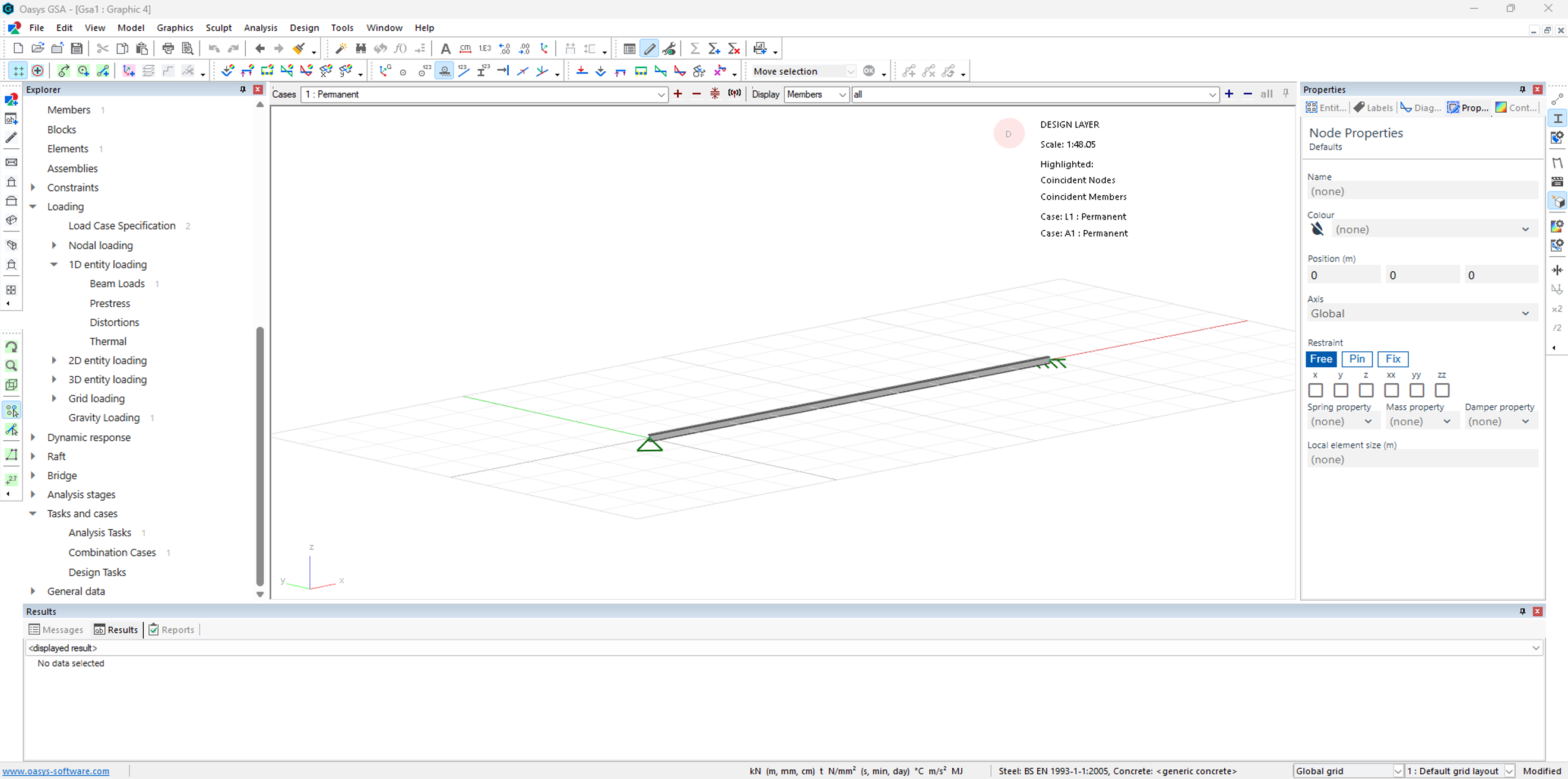
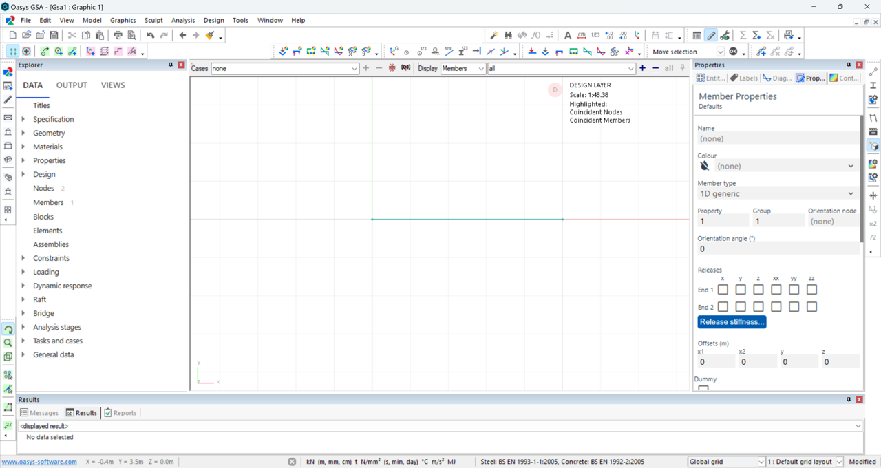
Click Finish and we can start modelling. You should now be able to see the graphics view as shown here.
Create a 1D member
- Click on the Add Entities icon
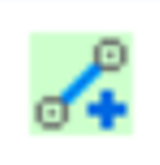 to add a 1D member.
 - Click on 2 points on the grid to create the 1D member, then right-click and select Quit operation to exit operation.
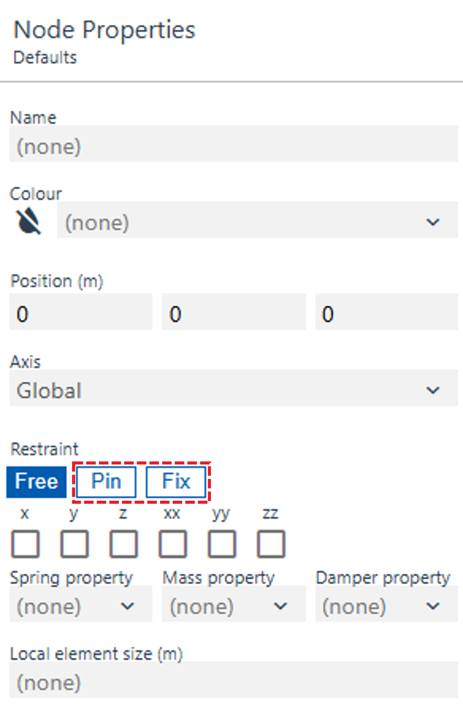
Add restraints to the 1D member
-
Click on the nodes icon
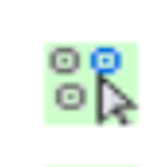 to add restraints to the member.
 -
The Node Properties panel should now appear on the right, select the first node and click Pin, then select the second node and click Fix.
-
Switch on the Label restraints
 icon to view the restraints.
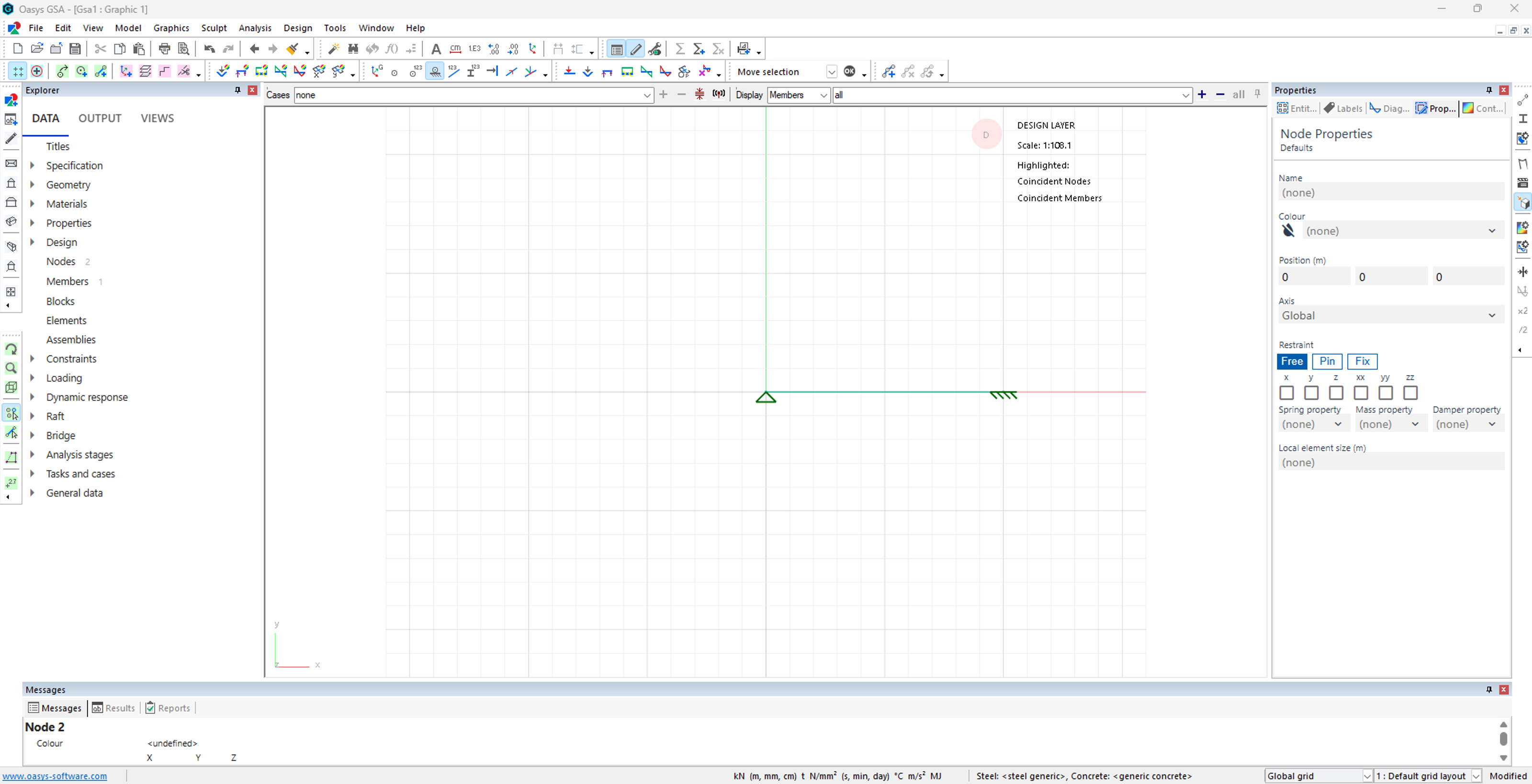
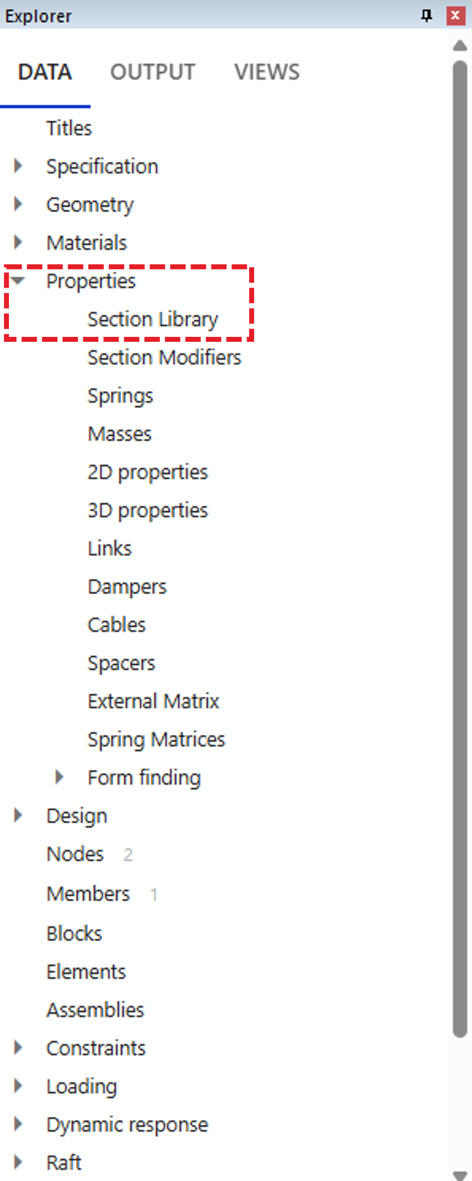
Add section properties to the 1D member
-
Select Properties → Section Library in the data explorer.
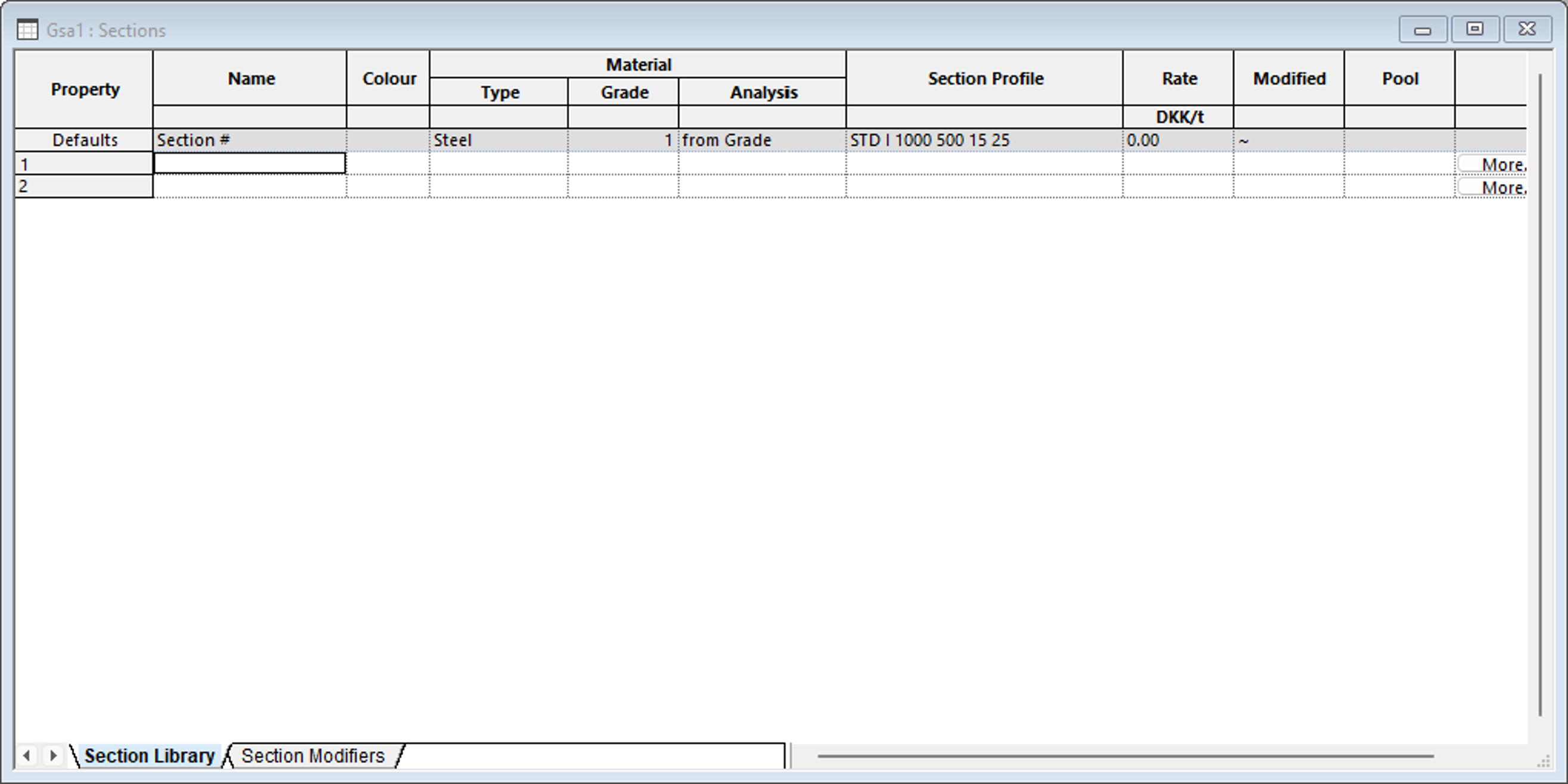
-
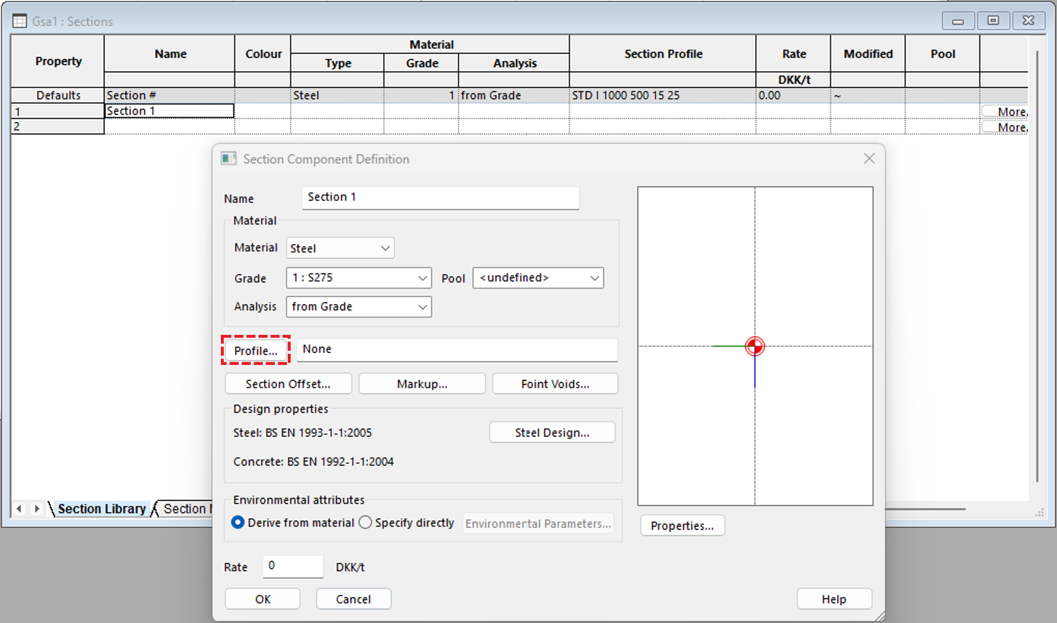
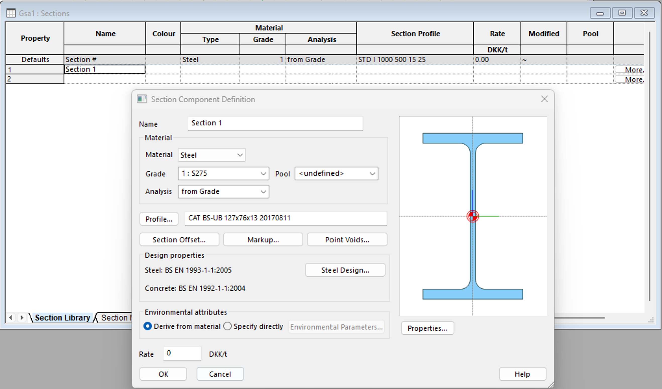
Double-click on the first empty cell and the Section Component Definition window pops up.
-
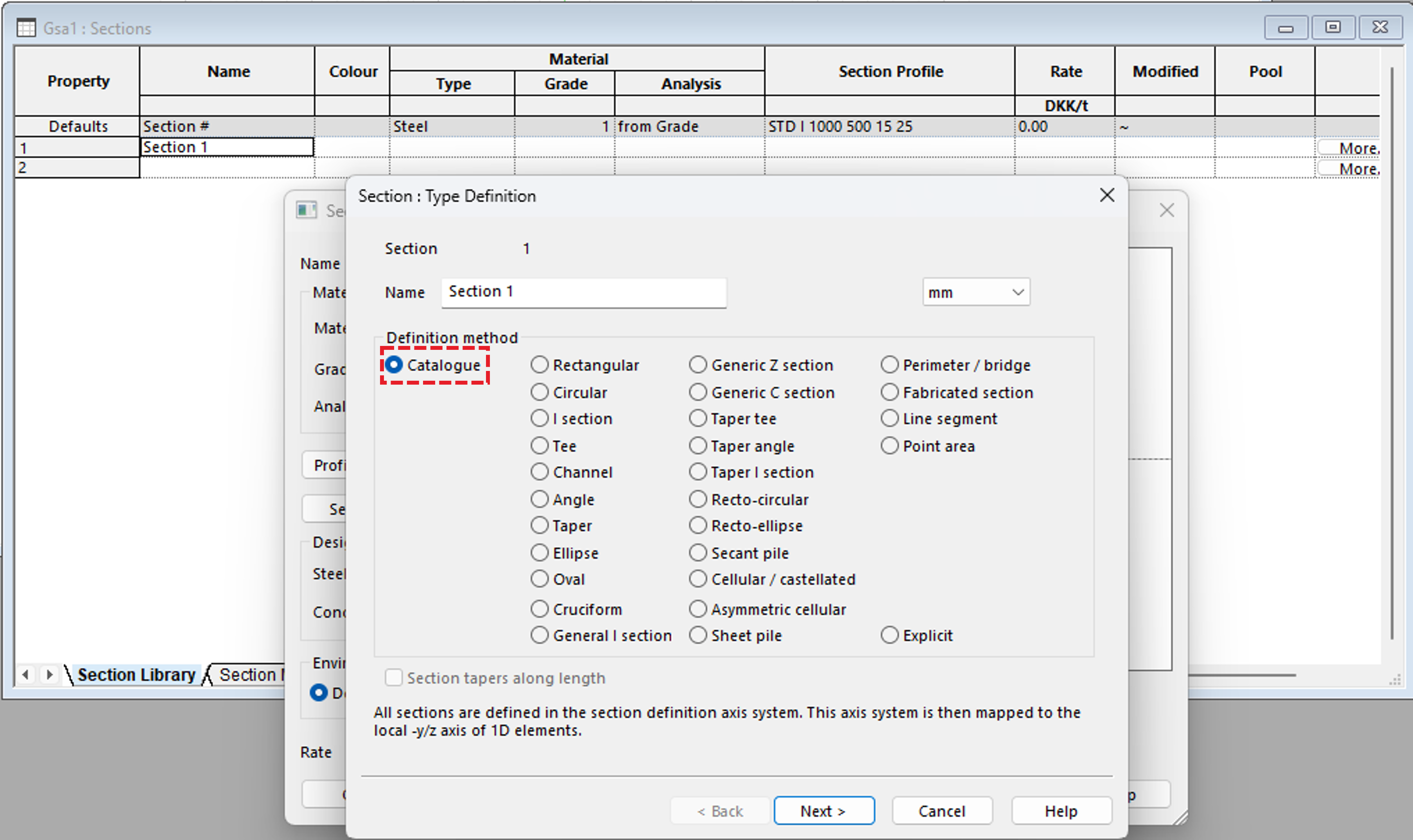
Select Profile and choose Catalogue, then click Next
-
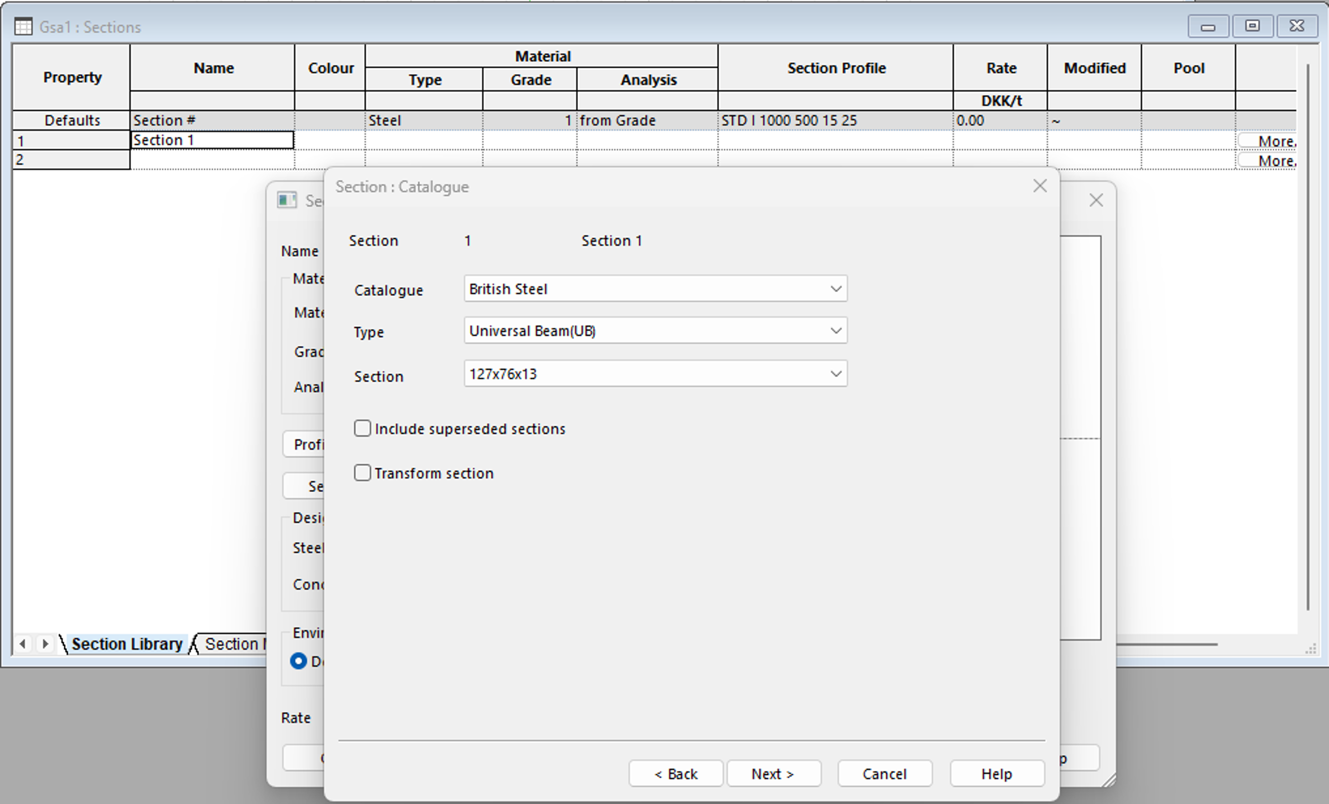
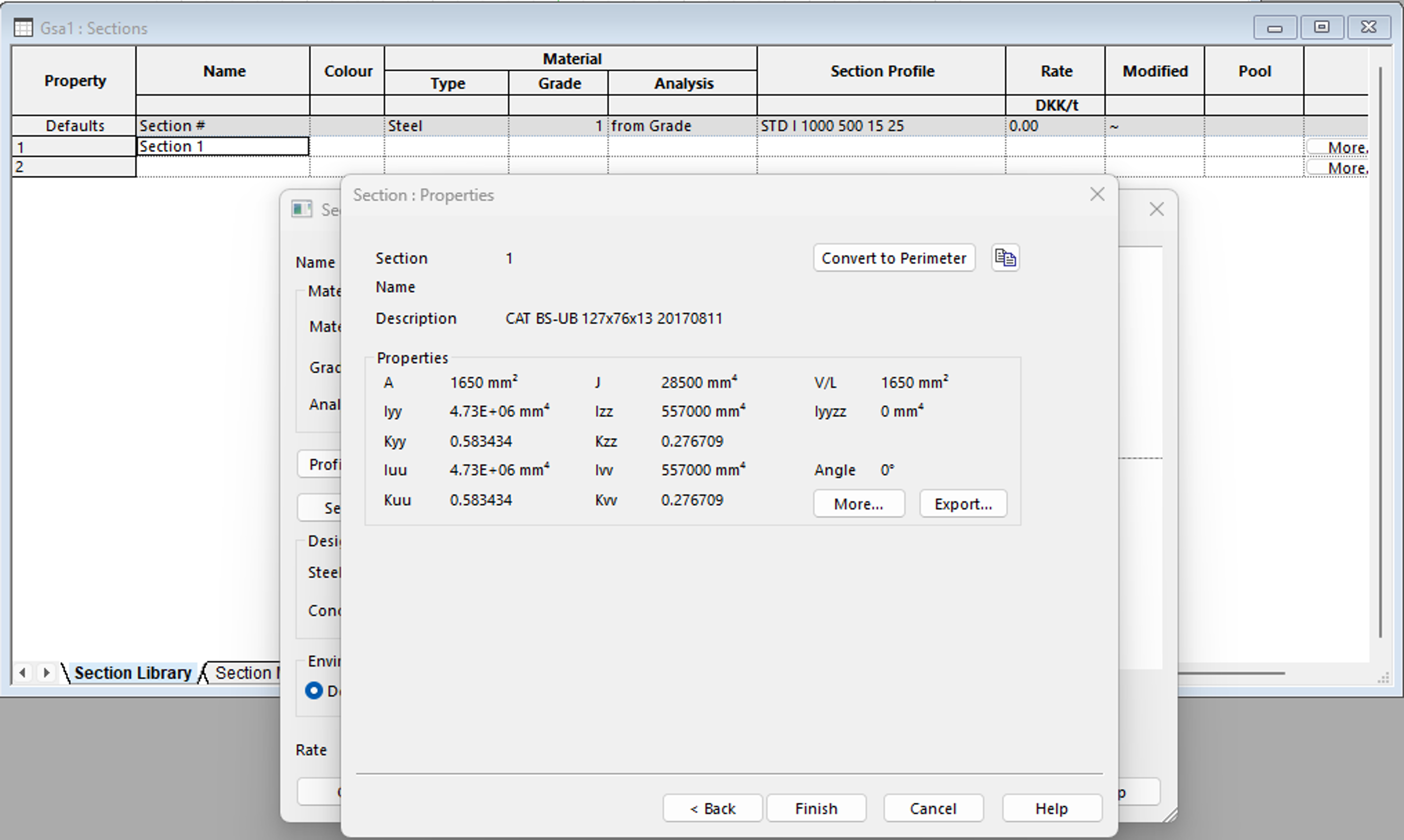
For the purpose of this tutorial we will choose Catalogue as British Steel, Type Universal Beam (UB), Section 127x76x13. Click Next to view the section properties associated with this section then click Finish and OK.
-
Navigate back to your graphics window by clicking on the Graphic view
 icon, then click on the Section display
  icon to view a 3D rendering of the section profile chosen.