4. Concrete frame
Model a concrete frame in GSA
This tutorial shows you how to model a concrete frame with concrete columns and a concrete slab. By the end of this tutorial you should be able to:
- Create 1D and 2D members, assign material and section properties to the members
- Add 2D face loads
- View properties in Design and Analysis layers
- Analyse and view results on 1D and 2D members
Create new model
-
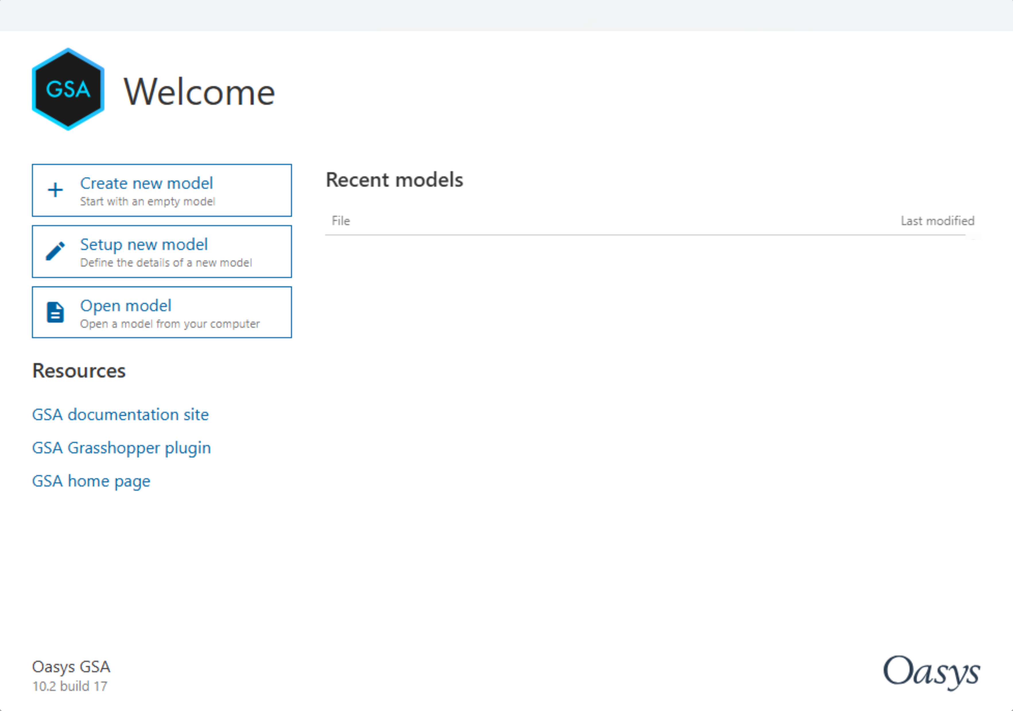
Open GSA and select Create new model
-
You will immediately be taken to the GSA interface.

-
Go to Data > Specification > Units and set up Units as appropriate then click OK. In this tutorial we will use kN-m as preferred units.

-
Go to Data > Specification > Design and select the Design code for Concrete Design. In this tutorial we will use BS EN 1992-1-1:2004 (GB). Click OK.

Create nodes and 1D members
-
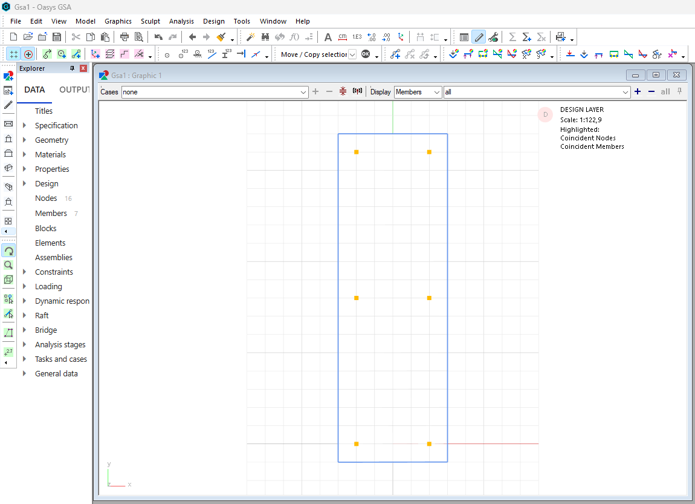
Starting in the Design layer, use the Add Nodes sculpt tool
 to add 2 nodes to the grid.
 -
Select the nodes using the
 icon or keyboard shortcut N. The nodes are selected when there is a purple square around them.
 -
Click on the Move/Copy
 icon to copy the nodes in the z direction. Input 4 and click preview to see the copy then click OK.
-
Use the create 1D entity
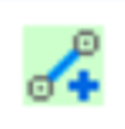 tool to create 1D entities, columns between the nodes. Right click to Quit operation. Now you have created 2 columns.
Duplicating the columns
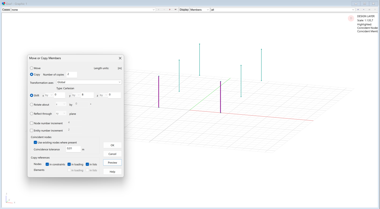
- Select your columns in the graphics window. Click the Move/Copy selection tool to duplicate them.
- In the dialogue box, set the number of copies to 2, set the amount to shift by 8m in the Y direction.
- Click OK to return to the graphics window. You should now see six columns. Rotate the view to inspect the columns by right-clicking and dragging.
Creating a 2D member in the design layer
Create the grid to draw your slab on
-
Select a node at the top of one of the columns. Right-click on this node and select Set current grid to this from the option menu. You will be asked if you wish to create a new grid plane.
-
Click Yes to create a new grid plane at the top of the columns.
Draw a 2D member to define the perimeter of your slab
You can now define the shape of your slab by drawing on the plane.
-
Select the Add entities tool

-
In the Properties pane, set the member type to 2D generic
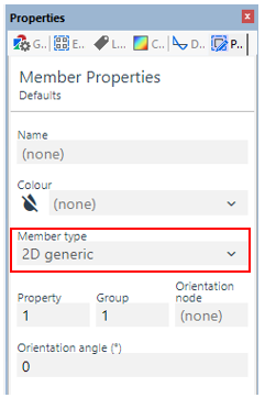
-
Click on the first corner of your slab. Continue clicking the other corners in either a clockwise or anticlockwise direction.
-
Finish by clicking back on the first corner. Right click and select Quit operation.
Tip: make sure the snap to grid points is on
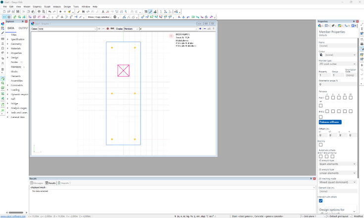
Define a void cutter member to create a hole in your slab
-
Select the Add entities tool
-
In the Properties pane, set the member type to 2D void cutter.
-
Similar to creating the slab, make a small rectangle in the centre of the larger one.
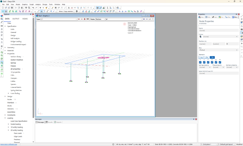
Set restraints
- Now we have completed creating the geometry. Set restraints by selecting the bottom nodes of columns and set the restraint as Fix. View the restraints using the Label restraints

Auto-meshing the slab
-
In the top menu, go to: Model > Coordination tools > Create elements from members or click
 button in the toolbar.
 -
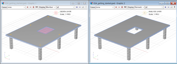
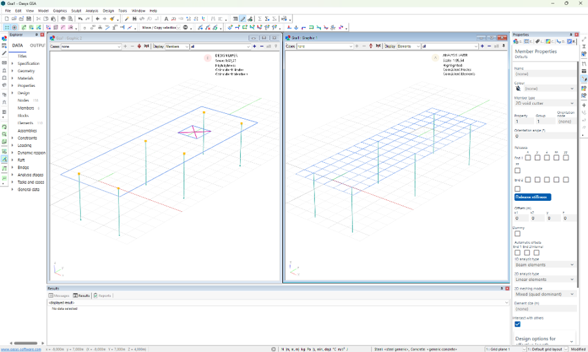
The members will be meshed into multiple quad and triangle elements.
-
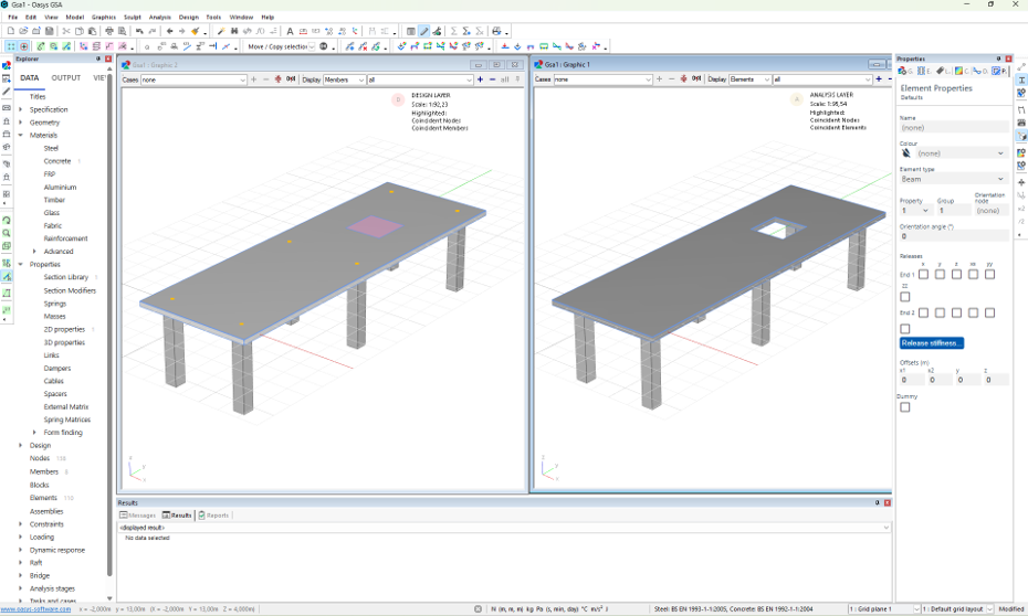
Switch to analysis layer to see the meshed slab. Or open another graphics windown and view the design and analysis layers side-by-side.
Setting section properties
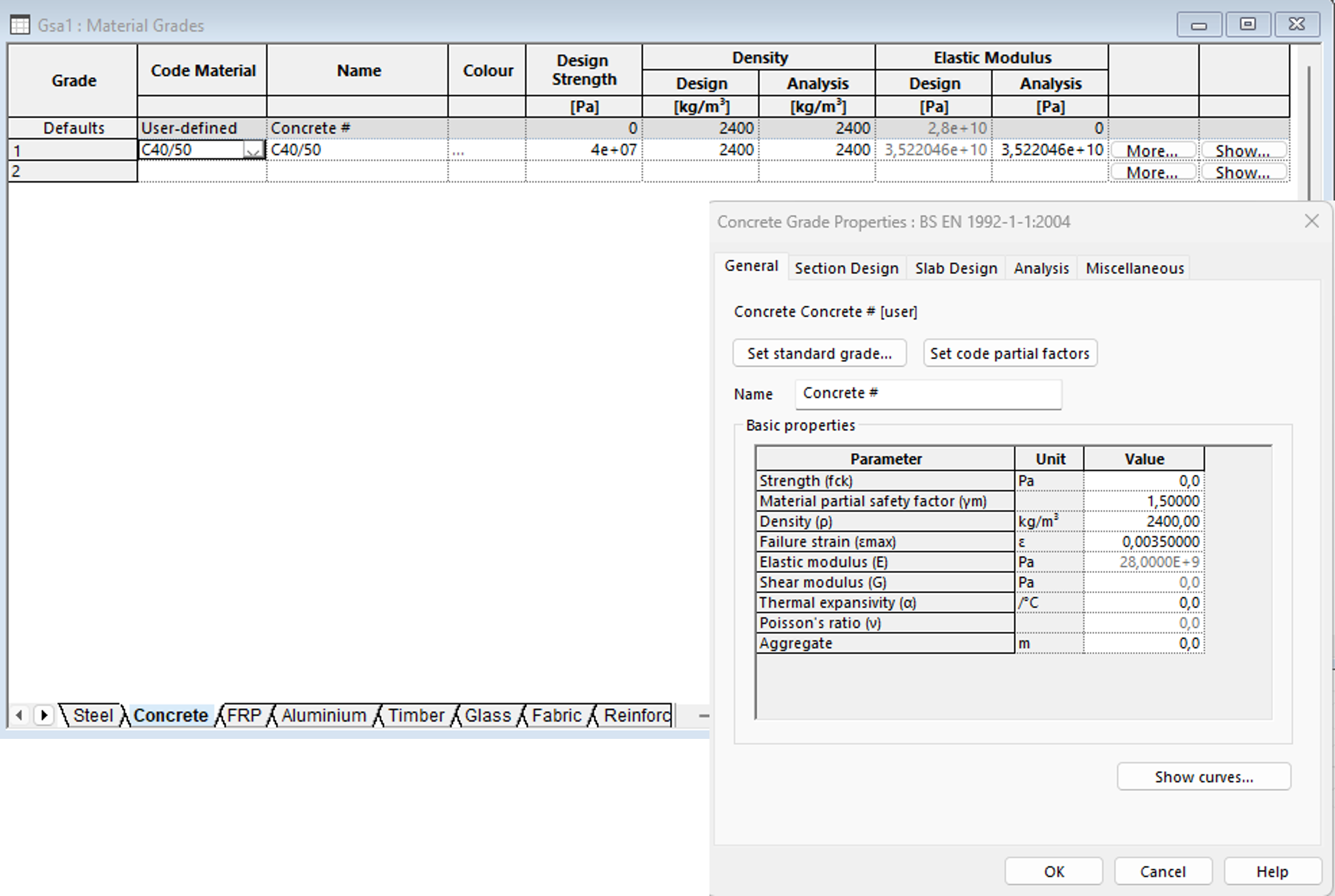
Set material properties
-
Go to Data > Materials > Concrete.
-
Double click on the first cell to bring up the Concrete Grade Properties window.
-
Click on Set standard grade and choose C40/50.
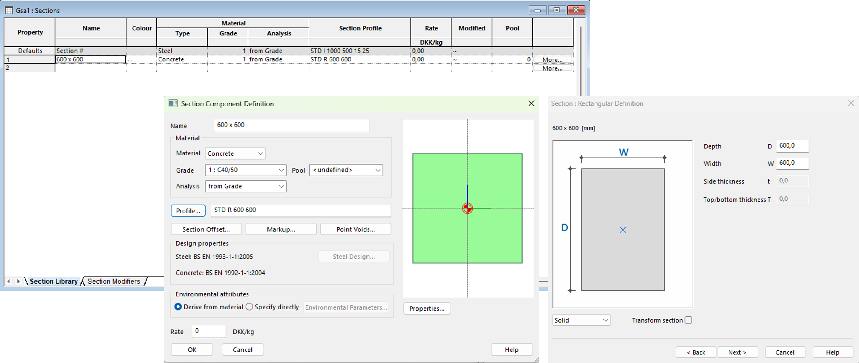
Defining concrete sections
-
Go to Data > Properties > Section Library.
-
In the next empty row of the table, click the first cell, then the Wizard
 icon.
icon.
Tip: You can also bring up the wizard by double-clicking the next empty row, or pressing Ctrl+W.
-
In the Name field type 600 x 600. Change the Material to Concrete which we just defined. Under Grade, you can either add the grade you defined earlier, or select Add code material to add another. Leave the analysis field as 'from Grade'.
-
Click Profile and tick Rectangular. Click Next and define the profile as 600 x 600. Click Next and Finish. The profile definition STD R 600 600 will appear in the profile field, with a sketch of your defined section on the right. Click OK to close the section definition wizard and return to the Section Library list.
Setting the properties of your slab
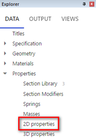
- Go to Data > Properties > 2D properties:
-
In the table that opens, click the first empty row and press Enter to fill the row with default values. Confirm the element type as shell, and the material as concrete. Check that the grade and analysis values are appropriate. Set the thickness of your slab to '250mm'.
-
Close the 2D properties table. Confirm that the red highlighting has gone from the elements table.

Check your element data in the graphics window
- In the graphics window, you should now be able to see that your slab is thicker by clicking on the Section display tool

- In the Properties pane, select the Labels tab. Click On elements and members, then, tick Element IDs and Property IDs:
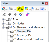
- The graphics view will now show the labels, and which associated property has been assigned to each element.

Note: The slab will have a property of PA1. You may need to zoom in to separate the text from the adjacent objects.
- Return to the labels tab of the Properties pane and tick Analysis material IDs.
- Items labelled as m0 shows the analysis material is derived from the material grade.
- Tick Material grade IDs in the Properties pane, to confirm your choices.
- Concrete material grades are prefixed with a c.
- In the labels tab, tick Element axes to confirm that the z-axis (blue line) of your slab is pointing upwards. If not go to Sculpt > Flip elements to correct it.