3. Portal frame
Model a portal frame in GSA
This tutorial will show you how to model a portal frame in GSA and by the end of this tutorial you should be able to:
- Create 1D members, assign material and section properties to the 1D members
- Add gravity, nodal and 1D entity loadings
- Analyse and viewing results through diagrams and data table

Creating a new model
-
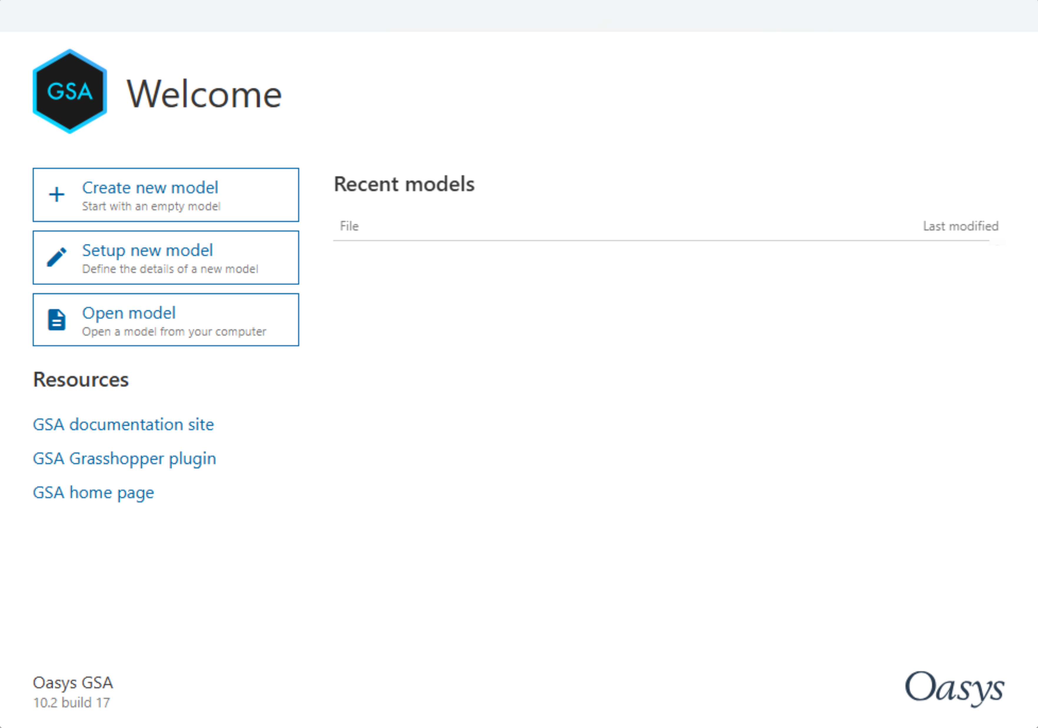
Open GSA and select Create new model
-
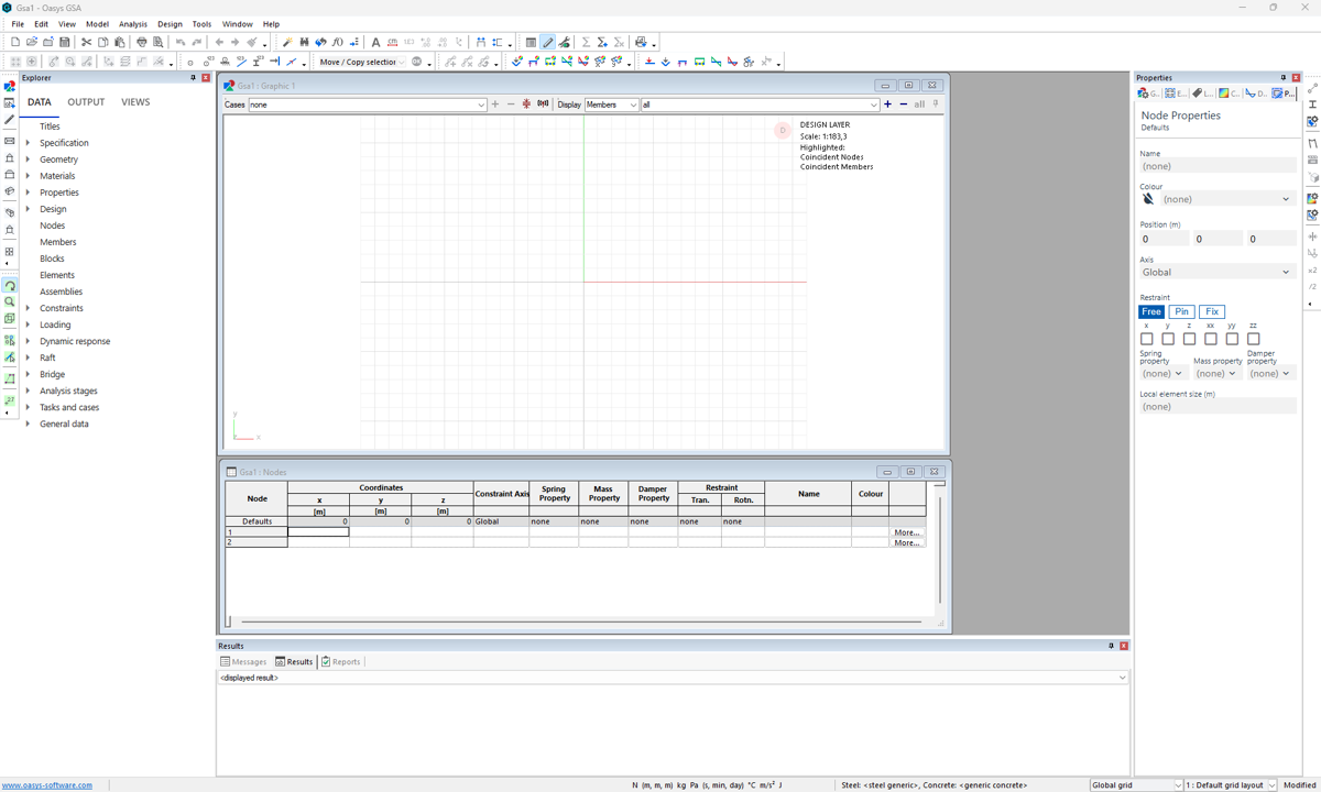
You will immediately be taken to the GSA interface

-
Go to Data > Specification > Units and set up Units as appropriate then click OK. In this tutorial we will use kN-m as preferred units.

Creating nodes and 1D members
Add nodes
-
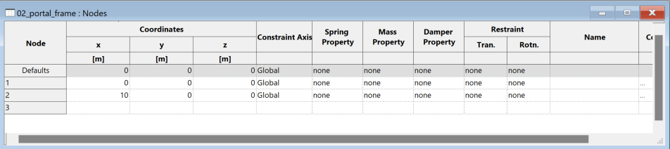
Go to Data > Nodes to open the nodes data table. Then drag the table below the graphics view.
-
Set the first node as (0,0,0) by clicking the first cell and press the Enter to copy all default values from the line above. In row 2, set the second node to be (10,0,0) by entering 10 as the x coordinate, then hit Enter to copy all subsequent default values.
Tip: To enlarge the font size in the table. Click Ctrl then scroll up using your mouse wheel.
- Click on the Add 1D entity scuplt tool
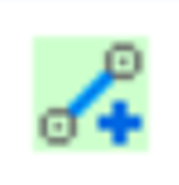 to create a 1D member between the two nodes.
This will bring up the Member Properties pane. Make sure the member type is 1D generic. Have a look at the dropdown to view the type of members that can be created. We will now create a 1D member by clicking on the two nodes. Right click to Quit operation.
Defining material and section properties to create a beam
-
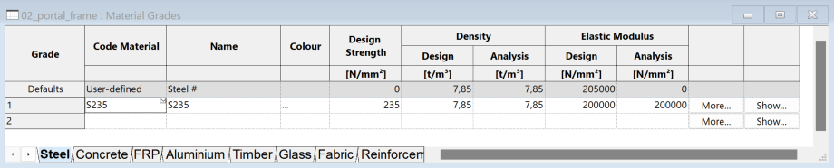
Go to Data > Materials > Steel to define a steel material property. Select code material S235.
-
Next go to Data > Properties > Section Library, double-click on the first cell or click on the More button found in the last column.
-
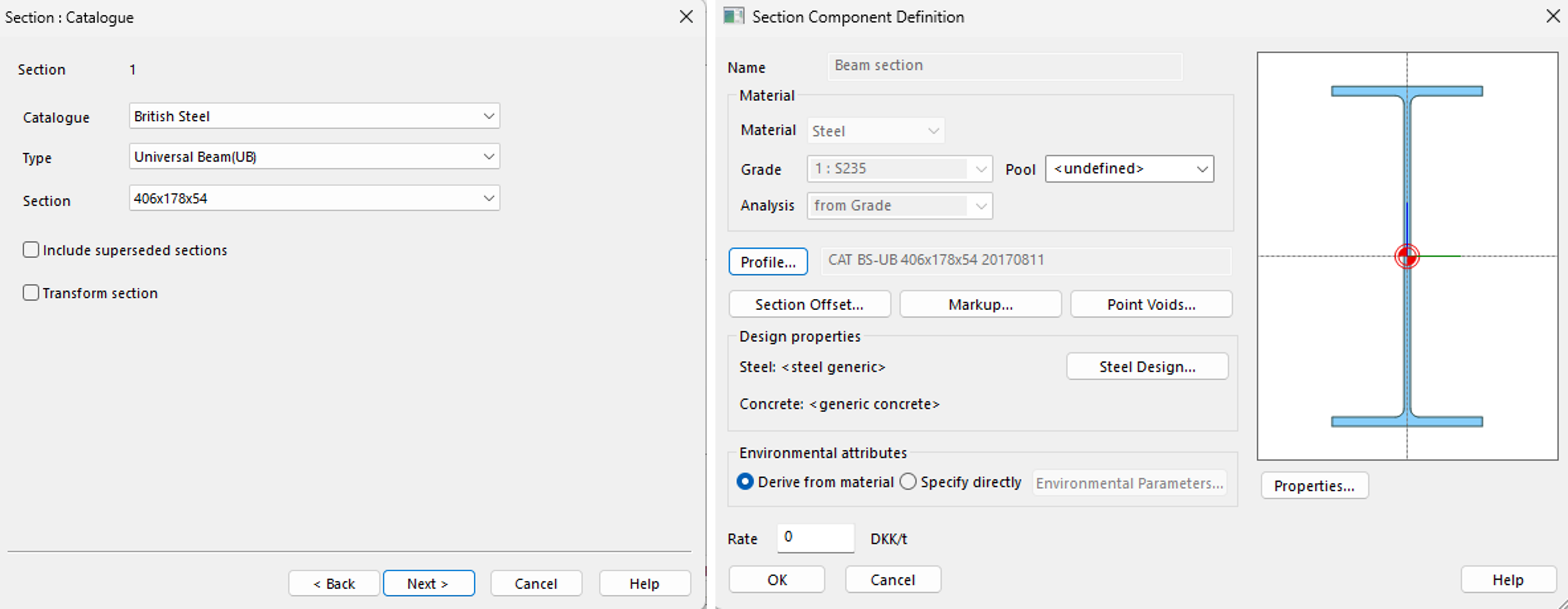
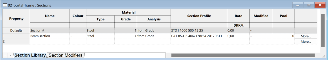
This brings up the Section Component Definition. Name the section Beam section or whatever you like. In Material, select Steel in the dropdown, this will choose the steel material that was just defined. Click on Profile and follow the guide to select a UB 406x178x54 steel section profile, then click OK. We will now find the defined section in the table.
-
Click the Element
 icon or use keyboard shortcut E to select the member that was created and assign the member to the property we just defined. It will be found in the Member properties panel and property dropdown. The beam is now created and has a material and a defined section.
Creating columns by extrusion for the portal frame
- Click the Nodes selection icon or use keyboard shortcut N. Drag or click to select the two nodes you have created. They will show as a purple square.

Note: The node coordinates and other settings will also appear in the Properties pane.
-
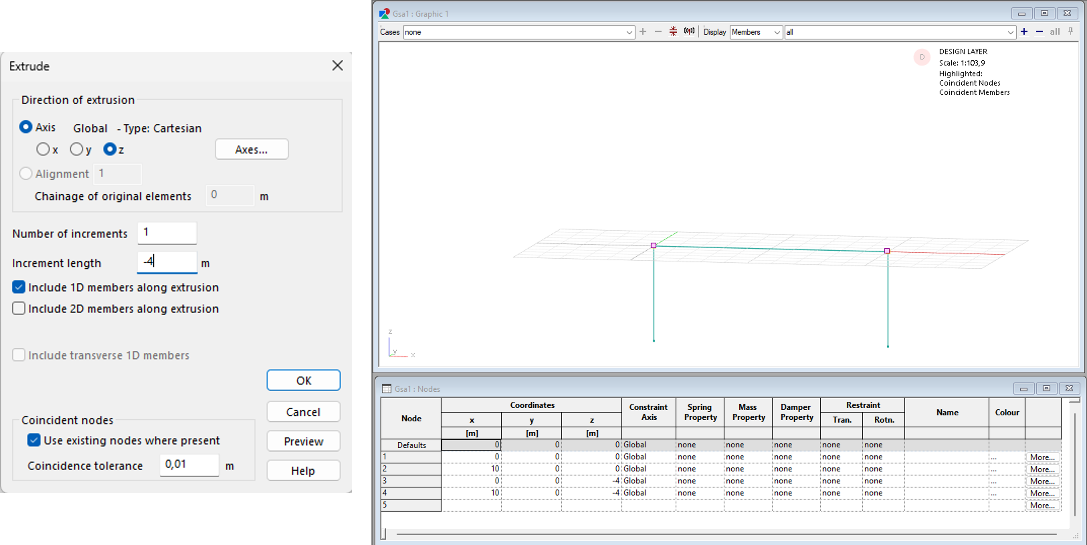
In the top menu, go to Sculpt > Extrude selection. In the extrude dialogue box, select your direction of extrusion axis (the default is z). Add the number of increments as 1 and increment length as -4.
-
Tick Include 1D members along extrusion. Click Preview to check your elements then OK. Two columns are now extruded from the selected nodes.
- Now create a column section UC 203x203x60 and assign this to the column by following steps 2-4 from creating the beam before.
Setting restraints
-
Click the Node select icon
 or use keyboard shortcut N. Select the nodes at the bottom of the columns to display the Nodes properties pane. Then go to Restraints > Fix to restrain the nodes.
 -
Select the Label restraints icon
 to show restraints in the graphics window.
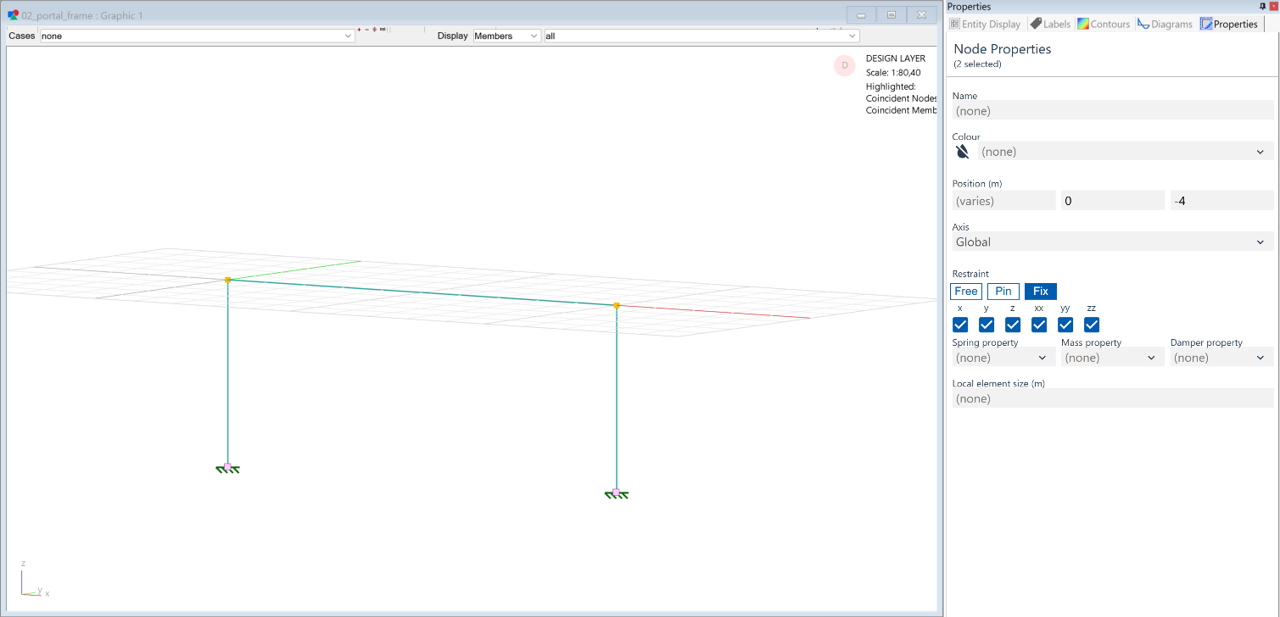
Inspecting members in the graphics window
-
The Resize to fit icon
 changes the graphic view. From here, you can click and drag the right mouse button to rotate the view.
 -
The Section display icon
 gives a 3D view of your structure.
 -
Use the Select elements/members icon
 to select a member and view its properties. These are displayed in the Messages pane (usually found at the bottom of the graphic window) and Properties pane (typically on the right).
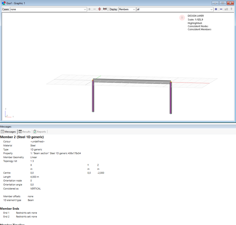
Mesh the model
Since we started by modeling the geometry in the Design layer, we will now need to create the corresponding elements needed for finite element analysis in the Analysis layer. This is needed in order to run the analysis and inspect applied loads, thus we recommend carrying out this step once the model geometry is created.
-
Go to the top menu. Select Model > Coordination tools > Create elements from members or click the
 icon in the toolbar.
 -
A dialogue box will appear. Set the member list to All, and press OK.
Note: You can now toggle between viewing the members in the Design layer and the analysis elements in the Analysis layer. To toggle between the layers, switch layers. To continue working with members, stay in the Design layer.