Applying loads to the portal frame
This section explains how to:
Load case specification
-
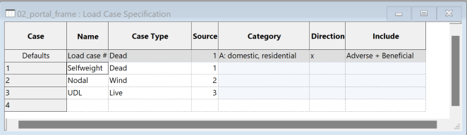
In Data > Loading > Load Case Specification we can define load case names and types of loads we want to define in the model.
-
Input appropriate names and case types for the self-weight, nodal and uniformly distributed loads. Make sure sources are numbered 1, 2, 3.
Adding self weight load
- Go to Data > Loading > Gravity loading. Click the first cell of row 1. Press Enter to copy the default row.
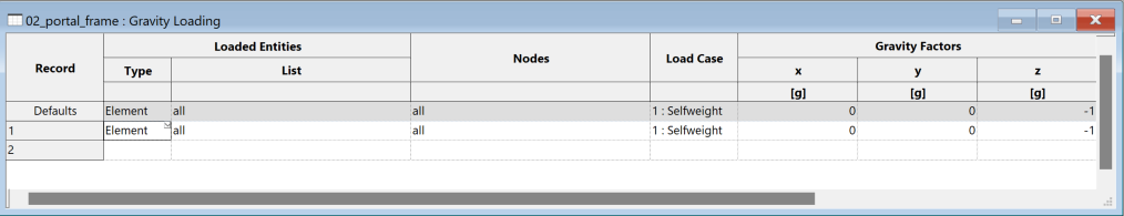
Note: This will calculate the self-weight based on the material density and element volume.
Creating a lateral load on a node
-
Select the node at (0, 0, 0) and press Ctrl+C to copy the selection.
-
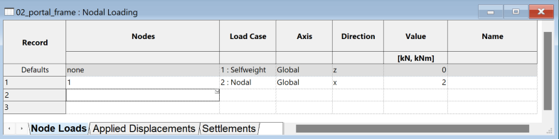
Go to Data > Loading > Nodal loading > Node loads to open the node loads table.
-
Select the first nodes cell on row 1, then press Ctrl+V to paste the node you have selected. Set the load case to 2 and change the direction of the load to x. Set your value to 2kN.
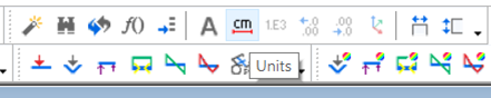
Tip: You can change the unit of your values via the units button in the top toolbar.
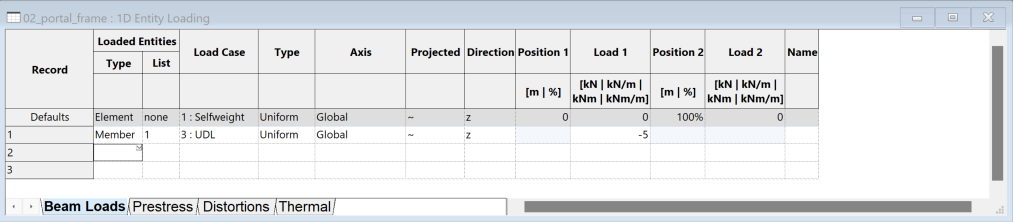
Creating a uniformly distributed load on a beam
-
Click the Select members/elements icon
 or use keyboard shortcut E to select your cross-beam and use the keyboard shortcut Ctrl+C to copy.
 -
Go to Data > Loading > 1D entity loading > Beam loads to open the Beam loads table.
-
Select Member in the Loaded entities type dropdown.
-
Use Ctrl+V to paste the selected member into the first cell. Set the load case to 3 and select uniform under Type. Specify the value of the load, e.g., -5kN/m in the z direction.
Tip: You can shrink the column size of the tables via the size columns to fit
button in the top toolbar or use keyboard shortcut Ctrl +Alt +C.
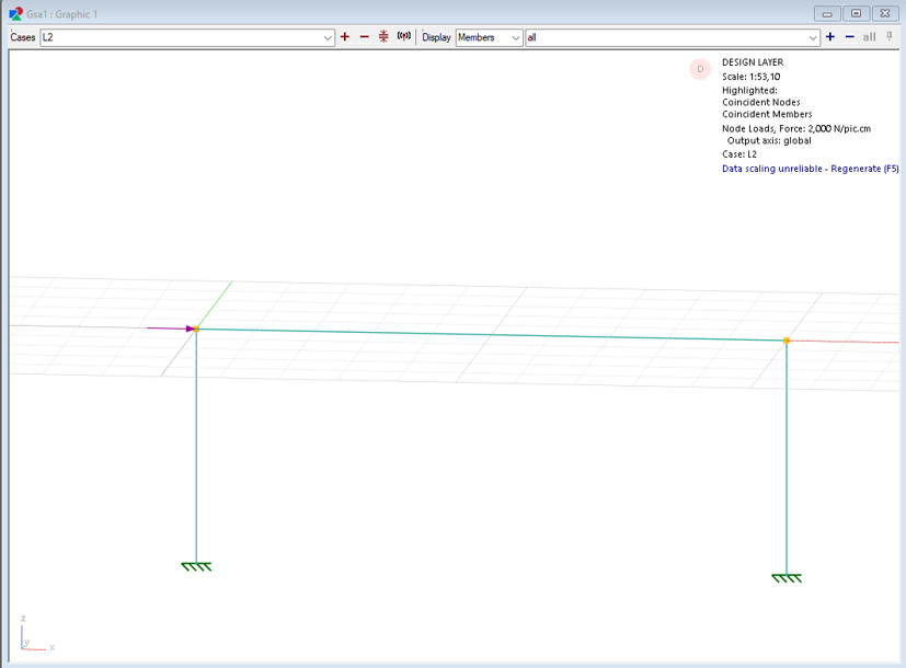
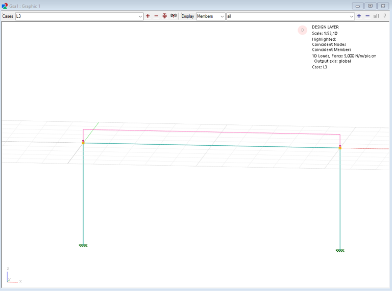
Display loads in the graphics window
- Go to the cases dropdown at the top of the graphics window and find loadcases L1, L2, L3. Click the Loads diagram icon
 and toggle through the dropdown to display the loads.
The node loads will be displayed as purple arrows while the beam load will be displayed as pink arrows.
Note: Loads can only be displayed if the analysis elements associated with the load have been created. If members are being loaded, its constituent elements need to first be created before it is possible to display the loads. See the mesh the model section for how to create analysis elements from members.