
Quick start guide

This entry introduces the GSA interface and the concept of layers in GSA.

GSA Interface

The image below shows the interface, with key components highlighted.
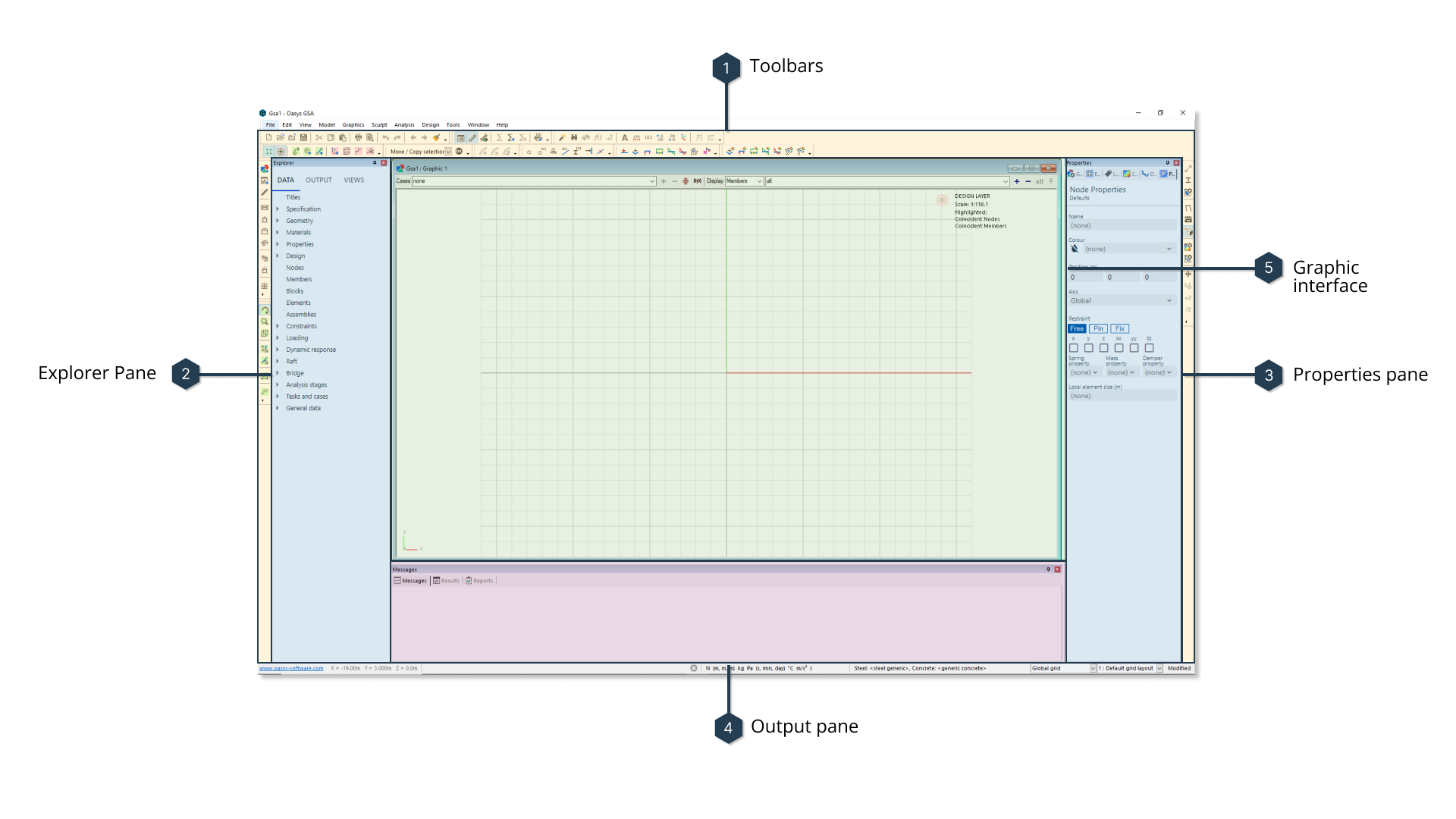
interface

These include:

  1. Toolbars: A shortcut to frequently used commands.
  2. Explorer pane: Where your model's data is contained.
  3. Properties pane: Edit your model's data here.
  4. Output pane: View messages, results and reports associated with your model.
  5. Graphic interface: Your model's structure is displayed here.

Actions in GSA can be carried out using one of the toolbar or pane options outlined above, or via a series of keyboard shortcuts. For a more comprehensive account of the interface, and these shortcuts, see the Explanations entries:

Concept of layers in GSA

There are two representations of the same geometric entity in GSA. BIM members are represented in the Design layer while finite elements of the same entity can be viewed in the Analysis layer.

Design layerAnalysis layer
design layer BIManalysis layer finite element

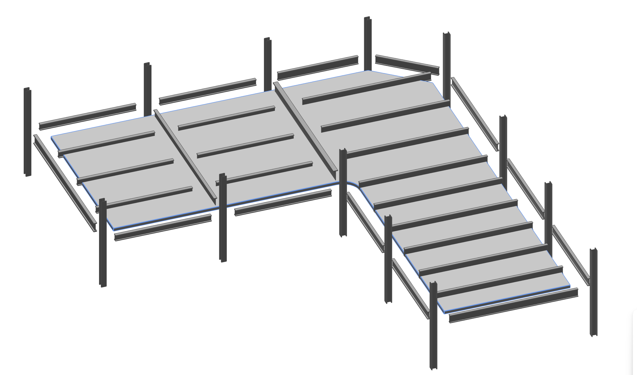
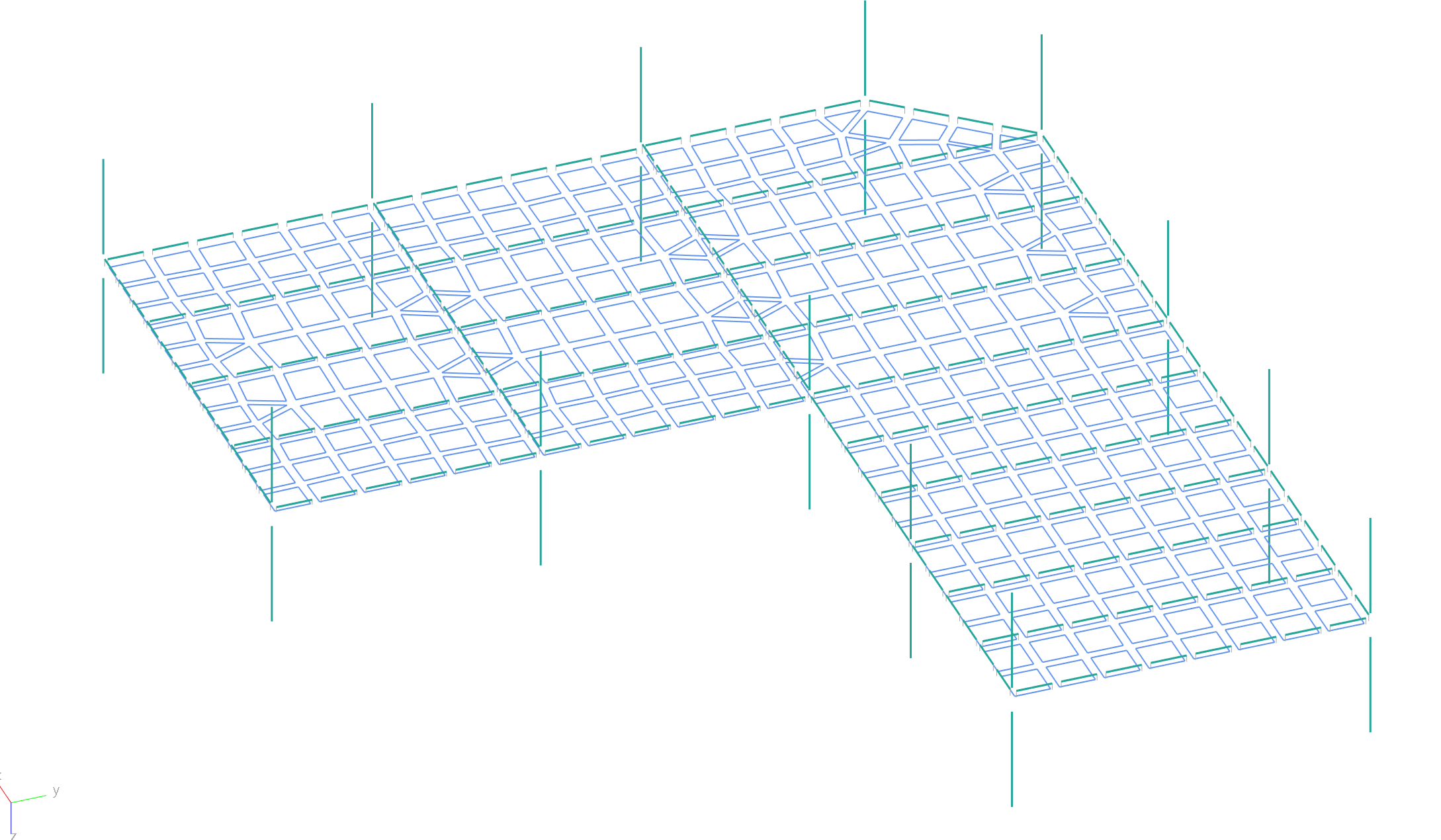
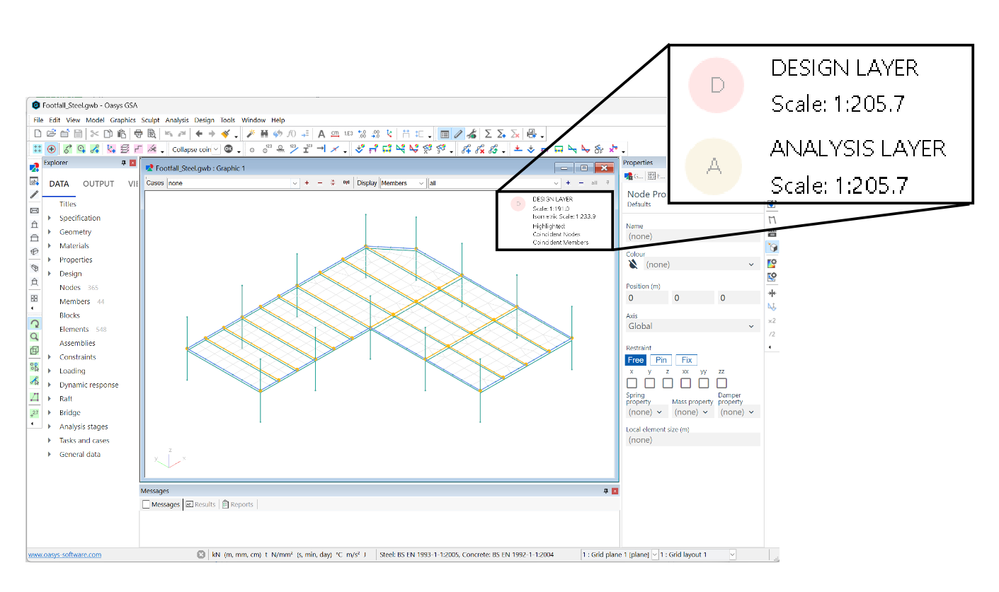
To identify the layer you are currently in, look at the top right corner of the graphics window. To change layers, right click anywhere in the window, and select Switch layer. You can also use the keyboard shortcut Ctrl+Alt+D to toggle between the layers.

design and analysis layers

See the Explanations entry on the Design and analysis layers for more on this topic.

Layers in GSA

The model exists in two layers: the Design layer represents the physical structure and the Analysis layer contains the actual finite elements to model the structure. Some items, such as nodes, may be mapped between the layers; others may exist only in one layer. The layers can be synchronised with one another using the coordination tools. You cannot change the analysis data while results exist that depend on that data.

The model can either be imported from a 3D modelling program or created within GSA in the Design layer, the Analysis layer, or both. Wizards assist the initial model creation and subsequent editing.

To identify the layer you are currently in, look for the following legend in the top right corner of the graphics window:

change-layer

To change layers, right click anywhere in the window, and select Switch layer.

You can also use the keyboard shortcut Ctrl+Alt+D.

Gif showing how to change layers.

Key graphics symbols

SyntaxAs described in this guideFunction
purplePurple circleSelected item
nodeBlue dotNode when it is connected to a member
unused-nodeRed squareUnused node
intersectYellow circleNode where members intersect
node-redRed dotCoincident node
red-arrowRed arrowElement x-axis.