1. Examining a GSA model
GSA offers various options to rotate and examine a model. You can access several of these via the toolbar options pictured below.
An introductory model to accompany this tutorial can be found in Sample models.
1. Default orientations for graphic view
The Orientation toolbar allows you to view the model from different default orientations. Click on the icons listed in the table below or use the corresponding keyboard shortcuts to show your structure in the desired view:
| Icon | View type | Keyboard shortcut |
|---|---|---|
| Plan | P | |
| X elevation | X | |
| Y elevation | Y | |
| Isometric | I | |
| Perspective | K |
2. Zoom
To zoom in and out of the model using the mouse scroll wheel.
3. Rotate
Rotate the model by holding down the right mouse button and moving the mouse, or by holding down the control key and click-dragging on the middle mouse wheel.
In addition, you can also use the cursor modes to help you navigate your model.
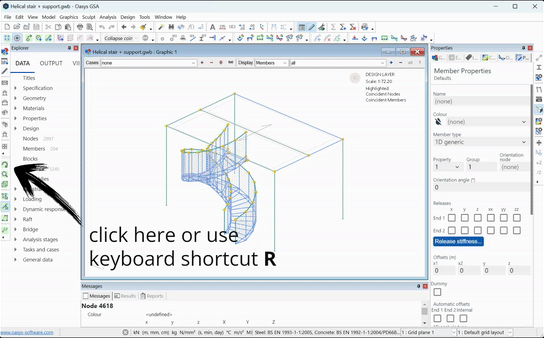
Access the rotate cursor mode via the Rotate  icon, or use the keyboard shortcut R. While here, you can rotate the structure with left click and drag. You can also select the centre of rotation using Ctrl+click on the node you want to rotate the structure about.
4. Volume - viewing a subsection of the model
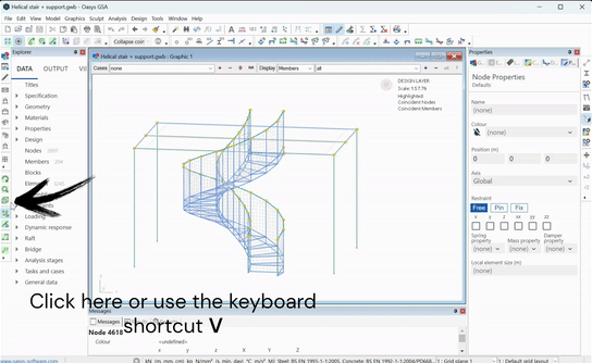
The volume cursor mode allows you to see a portion of the structure at a time. Click the Volume  icon or press V to enter this cursor mode. Click and drag a box around the portion of the structure you want to view (it removes everything else). To ‘go back’ to the previous ‘volume’, Ctrl+left click anywhere in the Graphic view.
Note that the click and drag behaviour follows the preferences set in https://docs.oasys-software.com/structural/gsa/references/hidd-pref-gr-sculpt/#definition.
icon or press V to enter this cursor mode. Click and drag a box around the portion of the structure you want to view (it removes everything else). To ‘go back’ to the previous ‘volume’, Ctrl+left click anywhere in the Graphic view.
Note that the click and drag behaviour follows the preferences set in https://docs.oasys-software.com/structural/gsa/references/hidd-pref-gr-sculpt/#definition.
5. Section display
You can also modify your view using the Section display  tool.
tool.
6. Shrink
And the Shrink  tool.
tool.
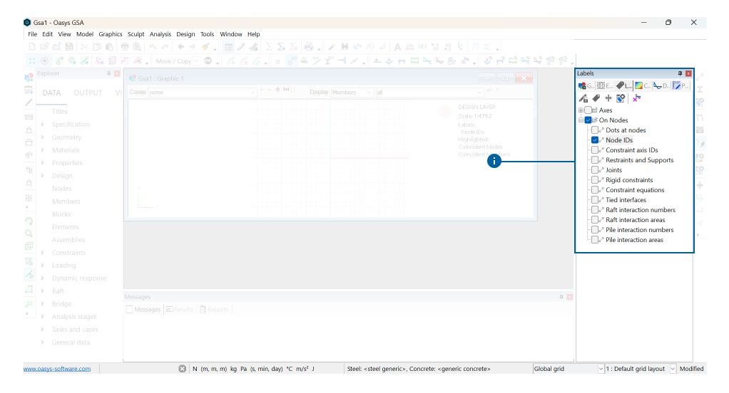
7. Labels
The toolbar below allows you to view restraints and releases
You can also activate element labels via the Labels tab inside the Properties pane for a complete list of labels available to toggle on/off.
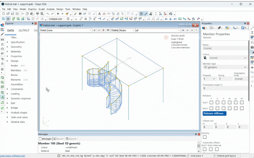
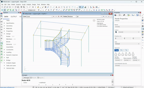
8. Select a node or an element
The toolbar on the left lets you select a node ![]() or an element
or an element  . You can view details of that node or element in the Messages tab in the output pane at the bottom of the interface.
Key graphics symbols
Actions in GSA can be carried out using one of the toolbar icons, property pane options, or via a series of keyboard shortcuts as described above. The following table describes the key graphical symbols you may encounter when modelling in GSA.
| Syntax | As described in this guide | Function |
|---|---|---|
| Purple circle | Selected item | |
| Blue dot | Node when it is connected to a member | |
| Red square | Unused node | |
| Yellow circle | Node where members intersect | |
| Red dot | Coincident node | |
| Red arrow | Element x-axis. |